Working with a JSON based API is incredibly easy, as a proof of this, I have quickly whipped up a 1 day build of a timeline time display.
The parts I used are essentially the standard parts that exist for the Arduino Platform.
– Arduino MEGA 2560 (Does not need to be a MEGA 2560, any Arduino should work just fine)
– Wiznet 5100 Ethernet Shield (This also works on the Wiznet 5500)
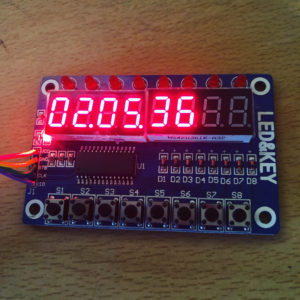
– TM1638 based 7 Segment Display board (Literally any Arduino compatible display can be used for this)
The hardware is pretty simple, attach the Ethernet shield to the Arduino, as per the instructions for that shield.
Connect the display to the Arduino. On my display, this was 5V, GND and three data pins – Strobe, Clock, DIO. The latter pins ended up as 5,6,7 on the Digital IO.
Thats it.
On the software side, Things are a little more in depth.
We will be using the JSON(dl) version of the API on Pixera.
What this means is that we can send any command from the API reference to the Pixera server, and so long as we add “0xPX” to the end, we will get a valid response.
If you follow the Ethernet examples in the Arduino system, once the ethernet library is set up, the code to send a JSON string is as simple as :
 if (!client.connected()) {
    client.connect(server, 1400);
  }

String TimelineHandle = "{\"jsonrpc\": \"2.0\", \"id\":49, \"method\":\"Pixera.Timelines.getTimelineAtIndex\", \"params\":{\"index\":0}}0xPX";
  if (client.connected()) {
    client.println(TimelineHandle);
  }
You will notice a couple of important points here:
– client is the Ethernet object declared to initialise the Ethernet shield.
– The server is connected on port 1400, declared in the connect statement.
– The string “TimelineHandle” contains the JSON string of the request.
– Every double quote in the JSON must be ‘escaped’ with a backslash if it is inside the string, otherwise the system will not compile.
– The command is sent with the “client.println” command, this adds a carriage return to the string that seems to make sure it sends correctly.
Pixera will respond immediately to this command.
To handle the response, we need to utilise the following code, which reads the response into a buffer:
String convertClientCommandToString( EthernetClient client ) {

  String clientCommand;
  clientCommand = "";

  if (client.available() > 0)
  {
    int h = client.available(); // length of the command ????

    for (int i = 0; i < h; i++)
    {
      clientCommand += (char)client.read();
    }

    return clientCommand;
  }
  else
  {
    return "#";//no commands // command length == 1 ???
  }
}
The code here simply waits for the connection to have available data, cycles through the incoming data and adds it to a String called “clientCommand”.
Once we have this string, we have a couple of options:
– Manually extract data from the response
– Use a JSON Library to deserialise it
The only hack I had to make is based on these two options.
Because the Arduino is a 8 bit microcontroller, the handles for objects, timelines and resources that Pixera sends will be too big for any of the variable types that exist on the platform.
To obtain a handle for the timeline (If you look closely, we requested the timeline handle in the JSON request) we need to slice up the string manually to get the timeline based on the fact we know where the value will be in the response.
command = convertClientCommandToString(client);
    for (int i = 0; i < 16; i++) {
      timelineIndex += command.charAt(34 + i);
    }
This is effectively cheating, but it does the job. Essentially just grabs 16 characters starting at character 34 of the string returned from Pixera.
At this point we know how to address the first timeline in Pixera, so we need to send a different command to the system to get the elapsed frames.
This is achieved the same way as the previous command:
String inChar = "{\"jsonrpc\":\"2.0\", \"id\":55, \"method\":\"Pixera.Timelines.Timeline.getCurrentTime\", \"params\":{\"handle\":" + timelineIndex + "}}0xPX";
    if (client.connected()) {
      client.println(inChar);
    }
The big difference to note here is that we have inserted “+ timelineIndex +” into the string (+ is a shortcut to concatenate strings and values in C) which is the handle value we just received from Pixera for the timeline.
The response from this is handled as per the previous one, with one difference, we use a JSON parser to extract values.
The Parser we will use here is ArduinoJson.
if (client.available()) {
    command = convertClientCommandToString(client);

    DeserializationError error = deserializeJson(doc, command);

    if (error) {
      Serial.print(F("deserializeJson() failed: "));
      Serial.println(error.c_str());
    }

    const char* jsonrpc = doc["jsonrpc"];
    unsigned long result = doc["result"];
The active ingredient here is the “deserializeJson(doc,command)”.
This part processes the JSON from “command” into and array of values called “doc”.
After this, the array references are turned into simple variables for easy manipulation.
A note here, the “result” variable holds the number of frames elapsed since 00:00:00:00
From this point, it is as simple as manipulating the frames into a readable HH:MM:SS:FF format for your display, which is fairly straightforward.
For bonus points, you can code another request that grabs the referenced timeline’s frames per second, and make the calculation dynamic based on the timeline FPS.
long getFPS(EthernetClient client) {
  String inChar = "{\"jsonrpc\":\"2.0\", \"id\":58, \"method\":\"Pixera.Timelines.Timeline.getFps\", \"params\":{\"handle\":" + timelineIndex + "}}0xPX";
  if (client.connected()) {
    client.println(inChar);
  }
  if (client.available()) {
    command = convertClientCommandToString(client);
    DeserializationError error = deserializeJson(doc, command);

    if (error) {
      Serial.print(F("deserializeJson() failed: "));
      Serial.println(error.c_str());
    }

    const char* jsonrpc = doc["jsonrpc"];
    long result = doc["result"];

    return result;
  }

}
I won’t go into the logistics of displaying on a display, as the one I used is very different to the simple 16×2 displays that are easily bought for the Arduino.